Dell Dimension Front Panel Connector
compiled by Robert Hancock, info collected by Doug (mitchedo) on DellTalk
This information is based on a Dell Dimension XPS P166s. I have received reports that the XPS R, D and T systems seem to use the same pinout, presumably the other systems do as well.
Some more information on this topic is available on this page.
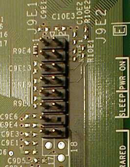
This picture shows the connector for the front panel power button, reset button, and power and hard disk lights: an 8x2 pin connector with 1 pin missing:
The table below lists the pinouts for the connector. The orientation of this table is the same as the picture above, this shows the top part of the connector. All the pins below pin 8 appear to be non-connected.
| 1: HD LED + | 2: Power LED + |
| 3: HD LED - | 4: Power LED - |
| 5: Reset | 6: Power |
| 7: Reset | 8: Power |
Each pair of pins labelled Power and Reset goes to the 2 wires for the corresponding button. The hard disk and power LED wires connect to the corresponding LEDs, you need to ensure the proper polarity of the + and - wires for each LED or it will not illuminate.
Because the pins for each pair of wires are adjacent to each other, it would be possible to put the board in a standard case and just plug the leads from the front panel over the correct pins. However most people want to go the other way, put a standard board in the Dell case. In that case you would have to go and splice the appropriate wires from the Dell front panel connector onto some 2-pin connectors and connect those to the appropriate headers on the motherboard. If you can find such connectors, of course. Doug's page (link at top) has some more info on possible solutions for this problem.